Voice Over 5G

Voice Over 5G

This White Paper discuss various methods to implement Voice and Video call services in the 5G network with the help of IMS network. Various message flows involved in establishing a call services in a 5G network are also discussed in detail.

1. Introduction

As 5G data services are rolling out, it is very much essential for telecom operators to provide basic services such as Voice/Video calls. To achieve the same, the 3GPP standards have defined that the 5G network must provide the Voice/Video call services using IMS. To deliver the Voice/Video service over 5G NR, the existing operators can either deploy the IWF (interworking function) in between existing IMS network and new 5G core, or upgrade the existing IMS network with 5G capabilities. However, the green field operators may go for building an IMS network with 5G capabilities.

During the initial phase of 5G deployment, i.e when service providers are delivering the 5G services using the option#3 (Refer: “5G Deployment options” whitepaper) existing 4G EPC and IMS network, will be used to deliver voice service for 5G subscribers. Later during the 5GC deployment service provider can deliver the voice services to 5G subscribers using Evolved Packet System Fallback (EPS FB).

As the time moves all operators will eventually roll out 5G coverage all over their service area. Operators can then integrate their existing IMS network to the new 5G systems to provide the Voice service using 5G Access network and 5G Core network. Note that, the radio technology in 5G is referred to as 5G New Radio, and the Voice/video call services using 5G RAN and 5G Core is referred to as Voice over New Radio- VoNR.

2. Different Method to implement Vo5G

There are different options available to implement VoNR in a network. Out of these options few of them will be suited for the existing operator and few others will be best for the greenfield operator.

2.1. Options for existing Operators.

An existing operator seeking to provide Vo5G services, eventually have to implement VoNR. If the operator has the following prerequisites then VoNR can be implemented using any of the different methods mentioned below.

Prerequisites for operators to implement VoNR:

  1. VoLTE service and IMS core network deployed and it is live.
  2. New 5GC and 5G NR coverage is available all over the service area.
  3. All the existing LTE nodes eNB are upgraded to gNB and connected with new 5GC.

Then,

The operator can consider the following methods to implement the VoNR

  • Method 1: Consider deploying a UDM in 5G core which supports HSS functionality for IMS as well.
  • Method 2: Deploy an IWF that convert diameter messages to HTTP and integrate the existing IMS network with new 5GC
  • Method 3: Update the existing IMS nodes to support the new HTTP based interfaces and connect the node with the new 5G core Network Functions.

Each of these methods has its own advantages and disadvantages, the operator can choose the best methods based on their priority.

2.1.1. Method 1:

This method incorporates Nodes with dual functionality for a smooth and faster roll out of 5G services by any operator. Most of the vendors have developed converged applications like UDM with HSS, PCF with PCRF. This helps the operator to connect the IMS network directly to the new 5GC without any change in their existing IMS network and less additional efforts. The only change required by the operator here is to make sure the diameter message related to the 5G subscribers are correctly routed to the 5G UDM and PCF with the help of a DRA.

Figure-1

2.1.2. Method 2:

An IWF node needs to be installed in between the 5G Network Functions and IMS core that can convert the HTTP messages to the diameter and vice versa.  This is required only if the new UDM network functions in 5G core does not support the diameter protocol. This method helps the operator to implement the VoNR solution quickly without disturbing the existing IMS network nodes.  But additional deployment and operational efforts will be required to implement and monitor the new IWF node.

Figure 2

2.1.3. Method 3:

The existing IMS network nodes need to be upgraded to support the HTTP services supported by 5G Network functions. All the IMS nodes in the network need to support the “Nhss_ims” service exposed by 5G core network functions.  This method helps the operator to avoid the footprints of older technologies in the 5G core.  This can be the ideal method for an operator who considers deploying a new IMS core as part of 5G deployment. 

Figure 3

2.2. Options for Green field Operators.

The green field operator may not have a 5G Core, 5G NR and IMS network deployed. So the best available choice for a green field operator is to deploy an IMS network that supports the HTTP interfaces along the new 5G Core and 5G NR deployment.

3. VoNR Scenarios.

This section explains the different real-time scenarios that occurs when a 5G user connects with the IMS network.

3.1. VoNR IMS Registration

IMS registration procedure is the first step that needs to be completed by a UE to get connected with the IMS network. As shown in the figure below the IMS registration procedure consists of four steps.

Figure 4

1. NR Attach:

The UE will get registered with the 5G network before it starts the registration process with the IMS network. This NR attach procedure is common for all 5G devices irrespective of the VoNR is supported by the device or not.  The figure below represents the various messages exchanged between different 5G nodes during the attach procedure. A detailed explanation of this attach procedure is not in scope for this discussion.

Figure 5

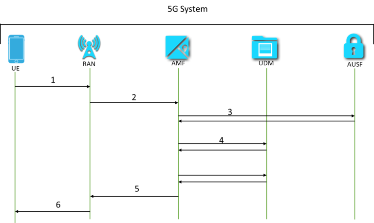
1.The UE sends a Registration Request to the 5G NR node with all the   details such as Registration type, SUCI or 5G-GUTI or PEI, last visited TAI (if available), Security parameters, Requested NSSAI, [Mapping Of Requested NSSAI], UE Radio Capability Update, UE MM Core Network Capability, PDU Session status, List Of PDU Sessions to be activate

2.After receiving the Registration request the RAN selects the appropriate AMF based on the  Requested NSSAI or based on the local operator policies and sends N2 messages to the selected AMF.

3.AMF selects an AUSF based on SUPI or SUCI and Initiate UE authentication procedure .After successful authentication, the AMF performs the NAS security initiation followed by NGAP procedure to provide the 5G-AN with security context.

4.and 5.The new AMF registers with the UDM using Nudm_UECM_Registration API and retrieves the Access and Mobility Subscription data, SMF Selection Subscription data and UE context in SMF data using Nudm_SDM_Get procedures. 

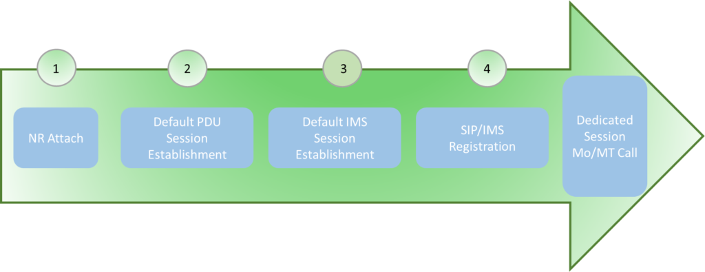
6.The AMF sends a Registration Accept message to the UE indicating that the Registration Request has been accepted. Now UE can initiate the default PDU session and IMS registration procedures. 

2. Default PDU session establishment:

After the successful completion of the initial attach UE will start the Default PDU session establishment procedure towards AMF. After the default PDU session establishment, the 5G user will be able to use the default services allocated for his subscription, generally the internet services. The messages involved in the PDU session establishment procedure are represented below.

Figure 6

  1. The UE initiates the PDU Session Establishment procedures towards AMF. The PDU Session Establishment Request includes a PDU session ID, Requested PDU Session Type, a Requested SSC mode, 5GSM Capability, PCO, SM PDU DN Request Container, [Number Of Packet Filters], Header Compression Configuration, UE Integrity Protection Maximum Data Rate, and [Always-on PDU Session Requested ]
  2. AMF selects the SMF from the network based on the S-NSSAI and DNN value present in the messages. If S-NSSAI value is not present then the AMF determines a default S-NSSAI of the HPLMN for the requested PDU Session either according to the UE subscription. Later AMF invokes the Nsmf_PDUSession_CreateSMContext and sends S-NSSAI of the Serving PLMN from the Allowed NSSAI to the SMF.
  3. SMF retrieves the Session Management Subscription data using Nudm_SDM_Get (SUPI, Session Management Subscription data, DNN, S-NSSAI of the HPLMN) and subscribes to be notified when this subscription data is modified using Nudm_SDM_Subscribe (SUPI, Session Management Subscription data, DNN, S-NSSAI of the HPLMN).
  4. After retrieving the subscriber information SMF creates an SM context and sends Nsmf_PDUSession_CreateSMContext Response to the AMF with an SSM Context Identifier. The SMF also selects one or more UPFs and the SMF allocates an IP address/prefix for the PDU Session
  5. If dynamic PCC is to be used for the PDU Session, the SMF contacts PCF based on the inputs from NRF or using a local configuration. The SMF performs an SM Policy Association Establishment procedure to establish a PDU Session with the PCF and get the default PCC Rules for the PDU Session.
  6. The SMF sends an N4 Session Establishment/Modification Request to the UPF and provides Packet detection, enforcement and reporting rules to be installed on the UPF for this PDU Session. The UPF acknowledges by sending an N4 Session Establishment/Modification Response.
  7. Finally Namf_Communication_N1N2MessageTransfer messages are send by SMF to AMF. The messages include the details of the PDU session created. The N2 SM information carries information that the AMF.
  8. AMF sends N2 PDU Session Establishment Accept with N2 SM information, PDU Session ID, N1 SM container and finally RAN allocates (R)AN N3 Tunnel for the PDU Session and forwards the NAS message received from the AMF to UE. Now the UE is allocated with the IP address and get connected with the data network.

3. Default IMS session establishment:

The steps involved in the IMS PDU Session establishment are the same as that of default PDU session establishment. In the IMS PDU session establishment, the DNN value provided by the UE will be representing an IMS network. Also if the UE is configured to discover the P-CSCF address during the IMS connectivity establishment, then the  UE shall include an indicator that it requests a P‑CSCF IP address(es). After the completion of the IMS Session establishment procedure, UE will know the         I-CSCF address.  After this UE establishes the path between CSCF then the UE starts the SIP/IMS registration Process.

Figure 7

4. SIP/IMS Registration:

Once the UE attaches to the network and PDU sessions are created successfully the UE must register with the IMS network. The IMS registration procedure includes IMS authentication and security negotiation between UE and IMS.

The IMS registration procedure will be completed in 2 attempts. In the first attempt, the IMS network will challenge User agent in the UE and in the second attempt, UE will get registered in the IMS network. After the SIP registration user will be able to make calls over 5G New Radio along with supplementary services. When a user makes calls, a dedicated PDU session will be established towards the IMS network. During and MO/MT call the SIP signaling will be carried by the default PDU session while the real voice/video data packets will be carried via Dedicated section.

First Attempt

Figure 8

  1. Using the IP address of P-CSCF received during the IMS default registration UE sends the SIP Register request message towards the P-CSCF with the IMPI, IMPU, and home network SIP URI.
  2. P-CSCF selects the I-CSCF and forwards the SIP Request towards the I-CSCF.
  3. I-CSCF queries the UDM to get the authentication information and also to get the details of the S-CSCF needs to be selected. The UDM returns the Subscriber authentication details and also the details required to select the S-CSCF address in response.
  4. I-CSCF then select the S-CSCF address based on the information such as SUPI and forwards the SIP register message towards the selected S-CSCF.
  5. S-CSCF fetches the Authentication vectors from the UDM. The UDM also saves the address of the S-CSCF node that serves the public user identity.  Since the user is not authenticated in the first attempt S-CSCF will reject the registration request with error code 401. In the error response the authentication vectors received from UDM are also send to UE.
  6. I-CSCF and P-CSCF forward the response from S-CSCF to the UE. Using the information received in the message UE will authenticate the network by verifying the authentication token (AUTN). The UE then generates the RES value and sends it back to the IMS network.

2nd Attempt

Figure 9

  1. After completing the IP-Sec connectivity with P-CSCF, UE sends the SIP registration message again towards the P-CSCF server port received in the 401 Unauthorized Message.
  2. P-CSCF passes the request message towards the S-CSCF.
  3. I-CSCF queries the UDM and gets the address of the S-CSCF node in which the UE is tried to register for the first time. 
  4. The I-CSCF forwards the SIP register message towards the selected S-CSCF.
  5. The S-CSCF compares the RES received in the SIP messages against the XRES stored. If it matches then S-CSCF downloads the subscriber profile from the UDM and UE gets registerd with the IMS network.
  6. The S-CSCF sends the 200 OK response message back to I-CSCF and I-CSCF forwards the same back to UE via P-CSCF. The P-CSCF then changes the temporary security association created during the registration to a new security association.  All further communication towards this UE will be using this association.
  7. To get notified on any default PDU session lost or disconnect the P-CSCF will subscribe to the PCF events for the subscriber.

3.2. 5G user calling 5G user

Below are the  procedures and network functions  involved in setting up a call between  two users in 5G VoNR coverage and registered in the IMS network. As shown in the figure  the IMS networks of both calling and called party will contact the PCF to initiate the establishment of dedicated bearer towards the UEs via the New Radio interface. 

Figure 10

All the SIP flows to establish a call between two users are the same as that of VoLTE call establishment.

  1. The calling party initiates the voice call by sending SIP INVITE request towards the B Party via P-CSCFs and S-CSCF. This SIP request includes SDP offer and IMS media capabilities. This SDM offer contains the bandwidth, codec details and other parameters required to establish a call. Upon receiving SIP INVITE messages every node acknowledges the previous node by sending 100 trying messages. The I-CSCF finds the S-CSCF address by contacting the UDM network function.
  2. When receiving SIP INVITE message the B-party sends SDP answer in SIP 183 Progress message. This message contains the codec details used by UE B. After receiving 183 sessions in progress message the P-CSCF  of  both B  and A party’s  network creates  a Dedicated bearer with QCI=1  on NR Network with the help of PCF in the 5GC network.
  3. The Originator (A) party sends the PRACK (Provisional Response Acknowledgement) which contains the details of the Final Selected Codec using for the calls. The called party (B) acknowledges the PRACK by sending the 200 OK.
  4. After receiving 200 OK messages The Calling (A) party sends SIP update messages to indicate that the resources have been allocated to establish the calls and B party acknowledges the same by sending 200 OK.
  5. The called (B) party starts to ring and the same has been updated to the calling party UE by sending a SIP 180 Ringing Message.
  6. When the B-party picks the call the same being informed to the A-party by sending 200 OK messages.
  7. The ACK represents that the call has been established and the traffic flows across the UE.

3.3. 5G user calling a 4G VoLTE user

The IMS system in 5G and 4G does not have any changes w.r.t the call connecting procedures. The signaling message flows to connect the 4G VoLTE user with the 5G NR user  is the same as that of 5G VoNR connecting with 5G VoNR.

Figure 11

As shown in the figure above all the procedure to establish a call between the 5G NR user and VoLTE user is the same as that of 5G user calling a 5G user.

3.4. 5G user calling to PSTN network

Like previous scenarios discussed the procedures involved in connecting the 5G NR user with a PSTN network is the same as that of 4G LTE network connects with the PSTN network. When 5G users calling the PSTN network number the SIP messages will get terminated at MGCF. Then the IMSMGW routes the control messages and data towards the PSTN network and helps the user to establish the call with the PSTN network.

Figure 12

  1. Calling party initiates the voice call by sending SIP INVITE request towards the B Party via P-CSCFs and S-CSCF. Since the S-CSCF cannot find the called party SIP URI the message will be routed towards BGCF for further processing. The BGCF forwards the same towards the MGCF and MGCF select an appropriate media gateway to route the messages towards the PSTN network. The MGCF then creates the H.248 address request towards IM-MGW with UE codec, IP address and RTP port number that is going to be used. The MGW allocates the requested and sends back the answer.
  2. The MGCF returns the 183 Session in progress message with a common codec List. Also MGCF requests the IM-MGW for a circuit switched port towards the PSTN network. After receiving the answer message back MGCF initiates ISUP message towards the PSTN network.
  3. The Calling party confirms the codec by sending PRACK towards the MGCF and MGCF accepts the codec by sending the 200 OK.
  4. After receiving 200 OK messages The Calling (A) party sends SIP update messages to indicate that the resources have been allocated to establish the calls. The MGCF replies with the message 200 OK. The MGCF later initiates ISUP COT messages towards the PSTN network.  The address complete message, ISUP ACM is sent back to MGCF from PSTN. The ACM message also indicates that the called party is being alerted.
  5. The MGCF forwards alerting indication in 180 Ringing messages towards the calling party (A).
  6. The Calling party (A) acknowledges the 180 ringing with a PRACK message towards MGCF. The MGCF acknowledges the same with 200 OK messages.
  7. When the called party answers, the PSTN network sends ISUP ANM message towards MGCF and MGCF requests IM-MGW to create a bidirectional connection towards the PSTN network. Once the bidirectional channel is established between the PSTN network and IM-MGW the MGCF sends 200 OK messages towards the calling party.
  8. The calling party sends an ACK representing that the call has been established and the traffic flows across the UE in NR to PSTN network via IM-MGW

4.Conclusion

The voice service in the 5G network can be realized using the existing IMS network by introducing a small change in the IMS or 5G core network functions. The IMS network has been deployed and used widely so the introduction of voice services in 5G network will hardly have any challenges. The IMS network provides the capability to the 5G user to interconnect with networks that still use older technologies. 

Leave a Reply