Network Function Virtualization in 5G

Network Function Virtualization in 5G

NFV is central concept in 5G technology. This paper gives a brief overview of NFV – its architecture, benefits and how 5G implements network slicing. It also describes steps in building an NFV Ready Network.

1. Introduction

NFV (Network Function Virtualization) is a concept to decouple network functions from proprietary hardware so they can run as software on standardized hardware and make the network more flexible by minimizing dependence on hardware.

Prior to NFV, to launch a new network service often required dedicated hardware, space and power; which resulted in increased costs of energy, capital investment challenges. The integration and operation of complex hardware equipment are difficult. Moreover, hardware rapidly reaches the end of life, requiring much of the procure design-integrate-deploy cycle to be repeated with little or no revenue benefit. Because of all these constraints

  1. Time to Market was high.
  2. Scalability was difficult to achieve.
  3. Management of all network nodes is not possible from a single point of presence.
  4. The reusability of Network function and hardware on which it is installed is not possible.

NFV helped in overcoming the above-mentioned limitations by leveraging standard IT virtualization technology to consolidate many network equipment types onto industry standard high volume servers, switches and storage, which could be located in Datacenters, Network Nodes and in the end-user premises.

Figure 1 : Classic Deployment vs Virtualized Deployment

2. Benefits

NFV offers below benefits to the operator network.

  1. Any new software can be developed and deployed without worrying much about hardware resources.
  2. New services can be instantiated and provisioned rapidly and dynamically across different geographical locations.
  3. Accelerate time-to-market by reducing the time required to deploy new networking services on remote sites over COTS hardware.
  4. Dynamic scaling is possible for services to handle high or low traffic.
  5. With the introduction of VNF(Virtual Network Function) Manager and Orchestration tools, it is easy to manage all the Network functions from a single point of presence.
  6. Hardware and network function reusability has become possible and easier.
  7. Multi-tenancy can be achieved to have dedicated virtual resources for different customers on the same shared physical resource layer.

3. NFV Architecture

The NFV architectural framework comprises of below functional blocks:

  1. Virtual Network Function
  2. Element Management System(EMS)
  3. NFV Infrastructure,
    1. Hardware and Virtualized resources
    2. Virtualization Layer
  4. Virtualized Infrastructure Manager(VIM)
  5. Orchestrator
  6. VNF Manager
  7. Operations and Business Support Systems(OSS/BSS)

Figure 2 : NFV Reference Architecture

4. Virtual Network Function

Virtual Network Function is a software implementation/package of NF which can be deployed over the virtualized infrastructure. The functional behavior and external interfaces of a Network Function deployed on Physical Resources known as PNF(physical network function) or on Virtualized Resources known as VNF(virtual network function) are the same Ex: vEPC(Evolved Packet Core), vIMS(IP Multimedia System).

A VNF can have multiple internal components called VNFC(Virtual Network Function Component). For Ex:-

  1. It can be deployed over multiple VMs(Virtual Machines) having a single component hosted on each.
  2. Whole VNF can be deployed over a single VM.

Figure 3 : Multiple VNFC Deployment

 Figure 4 : Single VNFC Deployment

5. VNFD – Virtual Network Function Descriptor

It is a deployment template that describes a VNF in terms of deployment and operational behavior requirements. It contains interface, connectivity and virtualized resource requirements. A VNFD has a one-to-one mapping with a VNF Package and it fully describes the requirements to deploy a VNF. NFVI resources are assigned to VNF based on requirements captured in the VNFD.

6. VNF Set and VNF- Forwarding Graph

The Network service which is virtualized can be implemented as a single VNF or multiple VNFs.When a group of VNFs is implementing a network service, there can be a scenario where some VNFs are dependent on other VNFs. The group of VNF having no interdependency is known as the VNF set. The group of VNF which requires data to flow in a specific sequence is known as the VNF-Forwarding Graph.

Figure 5 : Depicting VNF Set vs VNF Forwarding Graph

Ex of VNF Set:-  AMF and UPF in 5GC, here AMF is responsible for registration, connection and mobility management and UPF is responsible for routing user data packets. These VNFs work together to provide part of the 5GC functionality but work independently of each other.

Ex of VNF-FG:-  If we add SMF in the above-mentioned example, then UPF should process signaling packets only after it is being processed by SMF. This interconnection makes it a VNF-FG.

7. NFV Infrastructure

The NFV Infrastructure comprises of all hardware and software components which build up the environment in which VNFs are deployed, managed and executed. It can be spread across several locations. The network providing connectivity between these locations is also part of NFVI.

NFVI creates the virtualization layer which abstracts the underlying hardware so that it can be logically partitioned and can be utilized by VNF(s) to perform their functions. It also helps in building complex networks without geographical limitations.      

NFVI consists of:

7.1. Hardware Resources

This includes the physical hardware resources for compute, storage and network connectivity.

7.2. Virtualization layer and Resources

The virtualization layer is responsible for:-

  1. Abstracting and logically separating physical resources.
  2. Allowing the VNF to use the underlying virtualized infrastructure.

8. NFV Orchestrator

NFV Orchestrator creates, maintains and tears down Network Services of VNF themselves. If there are multiple VNFs, the orchestrator will enable the creation of end to end service over multiple VNFs. It is also responsible for the global resource management of NFVI resources. For example managing the NFVI resources i.e. storage, compute and networking resources among multiple VIMs in the network. The Orchestrator performs its functions by indirectly communicating to VNFs through VNFM and VIM.

8.1. Network Services

It is defined as connecting certain VNFs together to attain a defined behaviour.

9. VIM -Virtualized Infrastructure Manager

VIM provides functionalities to control and manage the interactions of VNF with computing, network, and storage resources. It supports multi-tenancy. Ex:- OpenStack, VMWare vCloud..

10. VNF Manager

VNF Manager is responsible for Life Cycle Management of VNF instances. A VNF Manager can be dedicated to the management of one VNF instance or for management of multiple VNF Instances. VNF Managers are assumed to be generic functions to support any type of VNF. However,  it can also support cases where VNF instances need specific functionality, and such functionality can be embedded in a VNF Package.

Below is some standard list of functions performed by the VNF Manager.

  1. VNF Instantiation.
  2. VNF Update/Upgrade.
  3. VNF Scaling out/in.
  4. VNF Healing.
  5. VNF Termination.
  6. Custom LCM tasks as per VNF instance needs.

The VNFM has a repository of available VNF Packages and their different corresponding versions, identified by the VNFD IDs. Ex: CBAM(CloudBand Application Manager), Cloudify Manager..

NFV is widely adopted by Telecom Operators.

11. NFV in 5G

A key aspect of 5G networks is network slicing. For Telco Service Providers, network slicing provides the ability to divide and scale the network on an as-a-service and ‘on-demand’ basis. This requires an advanced, software-defined infrastructure that allows multiple virtual networks to be created on top of shared physical infrastructure. Virtual networks then can be customized to comply with the needs of applications, services, devices, customers or other global TSPs.

In 5G networks, NFV will enable a network to be separated into multiple virtual networks that can support various types of services for the specific customer and vertical industries. Network slices will be isolated from one another, so the subscriber experience will be the same as if it was a physically separate network.

A network slice (NS) in this context is defined as a composition of dedicated compute, network and VNF/CNF(Cloud Native Functions), it can be spread across different geographical locations and it is associated with a set of operational policies and service level agreements (SLAs).

Figure 6 : Network Slicing using NFV

12. Building an NFV Ready Network

Setting up NFV Infrastructure includes the following steps:

  1. Setting up the hardware infrastructure(Storage, Computing, Networking)
  2. Creating Virtualization layer to abstract physical resources by Installing Hypervisor.
  3. Install Virtual Infrastructure manager(ex:- OpenStack) on top of the Virtualization layer.
  4. Instantiate VNF Manager(ex: CBAM).
  5. Uploading and Instantiation of VNF Packages on VNF Manager.

Figure 7 : Flow Diagram for NFV Ready Environment

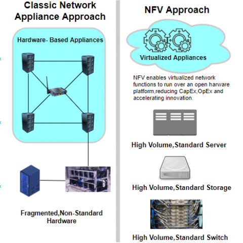
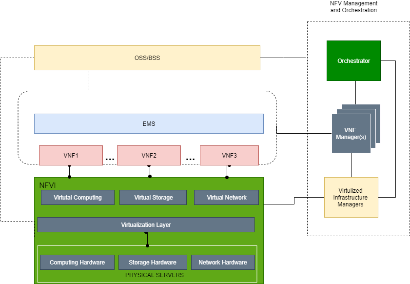
The computing hardware includes CPU and memory, which can be pooled across hosts present in clusters.  Storage can be locally added or distributed with devices such as network-attached storage. Network Hardware comprises pools of network interface cards and ports used by VNFs. None of this hardware is purposely built for any particular network function, but all items are instead generic hardware devices available as COTS.

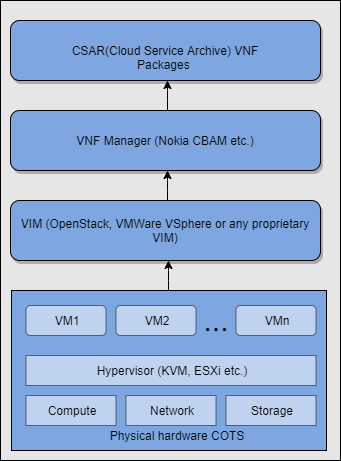
Hypervisors like KVM(Openstack) or ESXi(VMWare) need to be installed on bare metal servers to provide the virtualization functionality. The virtualization layer interacts directly with the pool of hardware devices, making them available to VNFs. The virtual machine on which VNFs are instantiated offers the virtualized computing, storage, and networking resources to any software that it hosts (VNF in this case) and presents these resources to the VNF as its own dedicated physical hardware.

OpenStack or VMWare vSphere needs to be installed on top of Hypervisor which will act as a Virtual Infrastructure Manager(VIM) for managing Virtualized Hardware. Any OpenSource tool can be used to install OpenStack ex:- PackStack, DevStack or Manual steps followed from Openstack Official website.

VIM directly manages the hardware resources, it has a full inventory of these resources and visibility into their operational attributes (such as power management, health status, and availability), also  the capacity to monitor their performance parameters(such as utilization statistics) .

To Instantiate VNFs we need VNF Manager to be installed. It can be installed as a VM on top of VIM or on a separate VM directly on top of Hypervisor or a COTS Hardware. Ex: Nokia CBAM, Cloudify Manager.

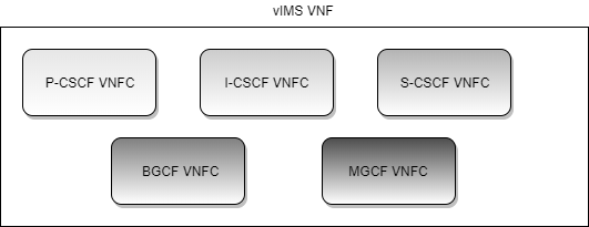
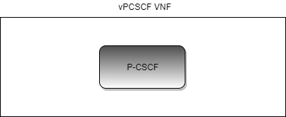
The VNF Packages provided by vendors need to be uploaded on VNF Manager which will be listed in the VNF Manager’s Catalog. VNF can be instantiated from the VNF Packages which are listed in VNF Manager Catalog.  Configurations specific to the VNF can be applied during instantiation using an input file. ex – JSON, XML. Basic Application and OS level configurations can be embedded in the VNF package using scripting templates. ex:- ansible, shell.

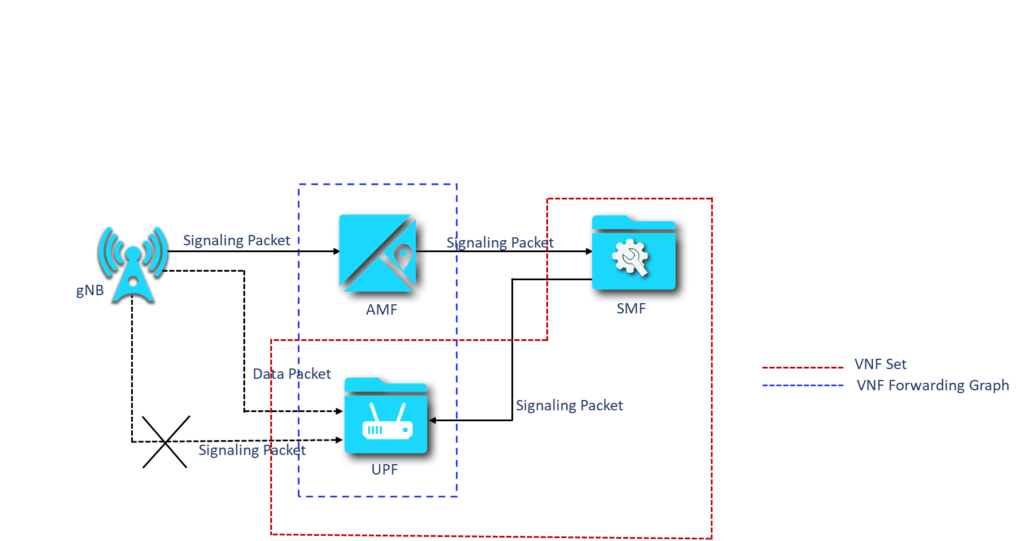
Now as the VNFs are up and running, operators need to assure the interconnectivity between VNFs and PNFs(if any) to achieve a fully functional network service.

With the help of the NFV orchestrator, the operator can predefine all these inter-connectivities and VNF configurations to automate the full Network service using YAML(Yet Another Markup Language).

This Post Has One Comment

  1. GOVINDA RAJ

    Excelletn

Leave a Reply